A Beginner’s Guide to 16x2 LCD Display Screen Pinout and Wiring
Add.: 2F, Bldg 10, Changfeng Industrial Park, Dongkeng, Fenghuang, Guangming, Shenzhen, China 518132
Mobile/WHATSAPP: 86-138 25769658
Email: marketing@topadkiosk.com topadkiosk@gmail.com
Skype: pghenry1
Wechat: adkioskhenry
English Web.: https://www.topkioskdisplay.com/
http://www.ad-kiosk.com/
https://www.toplcddisplay.com/
http://www.multitouchdigitalsignage.com/
https://www.youtube.com/channel/UCYVYNJHxLVEcQD8fuUxXNTA/videos?view_as=subscriber
https://www.facebook.com/TOPADKIOSKSHENZHEN/?ref=bookmarks
You often see the 16x 2 lcd display screen in various projects. The 16x 2 lcd display screen is great for showing system status, settings, and even custom characters. By following the correct pinout, you can connect each pin properly, which helps prevent wiring mistakes. The pinout for the 16x 2 lcd display screen is simpler than other LCD modules and it also consumes less power. This makes it a top choice for microcontroller projects. This guide provides easy steps to wire the 16x 2 lcd display screen to Arduino and other boards. You’ll learn both parallel and I2C connection methods. Plus, you’ll find troubleshooting tips, code samples, and clear diagrams. For more details, visit https://www.topkioskdisplay.com/.
Here is a quick look at some common uses:
Application
Description
Status Display
Shows system status and settings
Microcontroller Use
Works with Arduino, PIC, and others
Custom Characters
Lets you make special display symbols
Educational Projects
Used for learning and teaching
Key Takeaways
The 16x2 LCD display is easy to use and great for beginners. It can show up to 32 characters at one time.
Knowing the pinout is very important for correct wiring. Each pin does a special job that changes how the display works.
You can connect the 16x2 LCD to Arduino in two ways: parallel or I2C. I2C makes wiring easier and uses fewer pins.
Changing the contrast and backlight helps you see the screen better. Use a potentiometer to control the contrast.
Look at the wiring diagrams and code examples to set up your LCD display. These will also help you fix problems if they come up.
16x2 LCD Display Screen Overview
What Is a 16x2 LCD?
You will find the 16x2 lcd in many electronics projects. This lcd display shows information in a clear and simple way. The name "16x2" means the display has 16 columns and 2 rows. You can show up to 32 characters at one time. Many hobbyists and students use the 16x 2 lcd display screen because it is easy to connect and program. The lcd uses a special controller called the HD47780. This controller helps you send commands and data from your microcontroller to the display.
Here is a quick look at the main technical specifications:
Specification | Details |
|---|---|
Operating Voltage | 4.7V to 5.3V |
Display Bezel Dimensions | 72 x 25 mm |
Operating Current | 1mA (without backlight) |
PCB Size | 80L x 36W x 10H mm |
Controller | HD47780 |
You can use this lcd in many projects, such as clocks, temperature monitors, and simple games. This guide will help you understand how to use the lcd in your own projects.
Pixel Matrix and Display Features
The 16x2 lcd uses a pixel matrix to show each character. Each character appears in a 5x8 pixel grid. This makes the text clear and easy to read. You can display letters, numbers, and even custom symbols.
Some important features of the 16x2 lcd include:
You can display 16 characters per line, with 2 lines in total.
Each character uses a 5x8 pixel matrix for good clarity.
The lcd supports many character sets and lets you create custom characters.
The built-in backlight helps you see the display in low-light places.
You can adjust the contrast to make the text easier to read.
The lcd keeps the spacing between characters even, so your eyes do not get tired.
You will find that the 16x2 lcd is a great choice for learning and building new projects. This tutorial will show you how to connect, wire, and use the lcd display in simple steps.
16x2 LCD Pinout Guide
Pinout Diagram and Table
You need to understand the pinout before you start wiring the 16x2 lcd. The pinout diagram shows you where each pin sits on the lcd display. Each pin has a special job. If you connect the pins correctly, your lcd 16x2 will work as expected.
Here is a standard pinout diagram for the lcd 16x2. Most 16x2 lcd displays use this layout. You can use this table as a quick reference when wiring your lcd display.
Sr. No | Pin No. | Pin Name | Pin Type | Pin Description | Pin Connection |
|---|---|---|---|---|---|
1 | Pin 1 | Ground | Source Pin | Ground pin of the lcd | Connect to ground of MCU or power source |
2 | Pin 2 | VCC | Source Pin | Supply voltage pin of the lcd | Connect to supply pin of power source |
3 | Pin 3 | V0/VEE | Control Pin | Adjusts contrast of the lcd | Connect to variable POT (0-5V) |
4 | Pin 4 | Register Select | Control Pin | Toggles between command/data register | Connect to MCU pin (0 = Command, 1 = Data) |
5 | Pin 5 | Read/Write | Control Pin | Toggles lcd between read/write operation | Connect to MCU pin (0 = Write, 1 = Read) |
6 | Pin 6 | Enable | Control Pin | Must be high to perform read/write operation | Connect to MCU, pulse high for each operation |
7-14 | Pin 7-14 | Data Bits (0-7) | Data/Command | Send commands or data to lcd | Connect to MCU (4 or 8 pins depending on mode) |
15 | Pin 15 | LED Positive | LED Pin | Powers lcd backlight | Connect to +5V |
16 | Pin 16 | LED Negative | LED Pin | Completes backlight circuit | Connect to ground |
Tip: Always double-check your pinout diagram before wiring. Mistakes can cause the lcd 16x2 to show a blank screen or garbled text.
You can see that the lcd 16x2 has sixteen pins. The first six pins control power and operation. Pins 7 to 14 are data pins. Pins 15 and 16 power the backlight. This pinout helps you wire the lcd display to your microcontroller with confidence.
Pin Functions
Each pin on the 16x2 lcd has a unique function. You must know these pin functions to wire your lcd display correctly. The pinout diagram gives you the location, but the pin functions explain what each pin does.
Here is a breakdown of the main pin functions:
Ground (Pin 1): This pin connects to the ground. It completes the circuit for the lcd display.
VCC (Pin 2): This pin supplies power to the lcd 16x2. You connect it to a 5V source.
V0/VEE (Pin 3): This pin adjusts the contrast. You connect it to a potentiometer to make the display easier to read.
Register Select (RS, Pin 4): This pin separates data from commands. You set it LOW for commands and HIGH for data. This helps the lcd 16x2 know what to display.
Read/Write (RW, Pin 5): This pin sets the operation mode. You usually keep it LOW for writing. This makes the lcd display accept data from your microcontroller.
Enable (EN, Pin 6): This pin latches incoming data. You send a short pulse to this pin for each data transfer. This step is crucial for the lcd 16x2 to work.
Data Pins (D0-D7, Pins 7-14): These pins carry the data and commands. You can use all eight pins for 8-bit mode or just four pins for 4-bit mode. Using fewer data pins saves space on your microcontroller.
LED Positive (Pin 15): This pin powers the backlight. You connect it to +5V through a resistor.
LED Negative (Pin 16): This pin completes the backlight circuit. You connect it to ground.
Pin | Function Description | Impact on Wiring and Operation |
|---|---|---|
RS | Separates data from commands | Essential for correct display operation |
RW | Sets read or write mode | Usually held LOW for writing |
EN | Latches incoming data | Needs a pulse for each transfer |
D0-D7 | Data bus pins (can use 4 or 8) | Impacts number of microcontroller pins needed |
LED+ | Powers backlight | Affects visibility of lcd display |
LED- | Completes backlight circuit | Essential for backlight operation |
You can see how each pin affects the lcd 16x2 operation. If you wire the pins correctly, your lcd display will show clear text and symbols. If you mix up the pinout, the lcd 16x2 may not work. This guide and tutorial help you avoid common mistakes.
Note: The lcd 16x2 works best when you use the correct pinout diagram and understand the pin functions. Always check your wiring before powering up your lcd display.
You now have a clear view of the pinout and pin functions for the 16x 2 lcd display screen. This knowledge prepares you for the next steps in wiring and programming your lcd 16x2.
Wiring lcd 16x2 to Arduino
Components Needed
You need a few basic parts to start your lcd 16x2 wiring project. These components help you build a stable connection and make your lcd display work with Arduino. Here is a list of what you need:
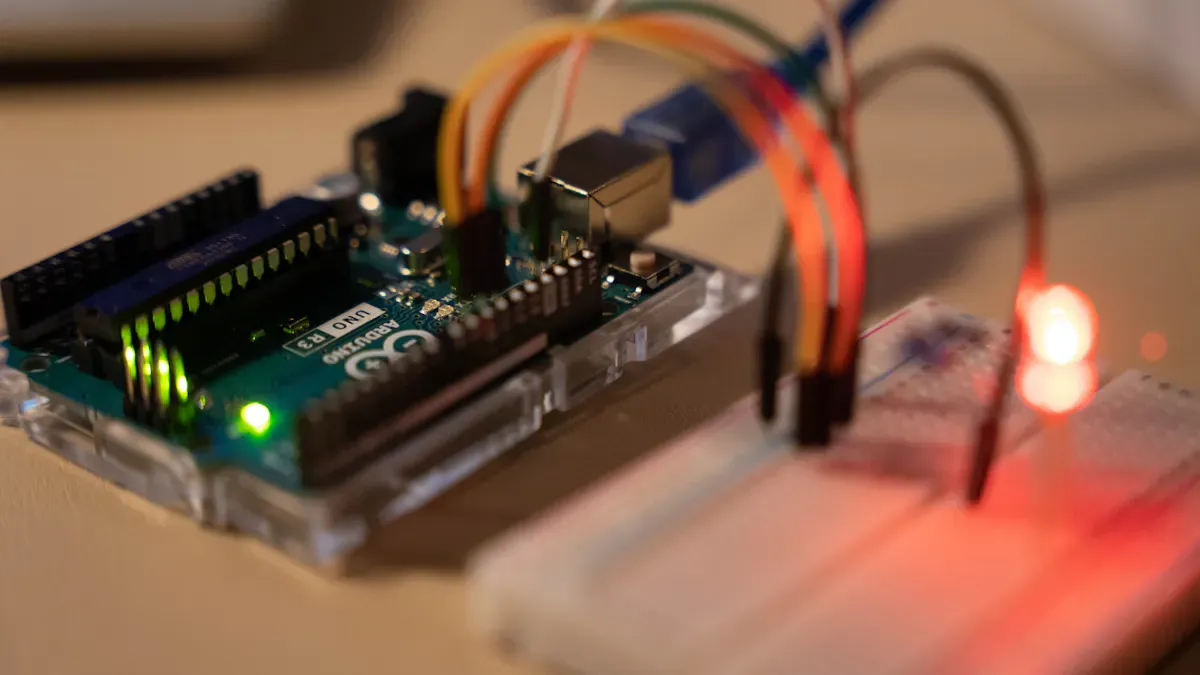
Arduino board (such as Arduino UNO, Nano, or Mega)
16x2 lcd display
Breadboard
Jumper wires
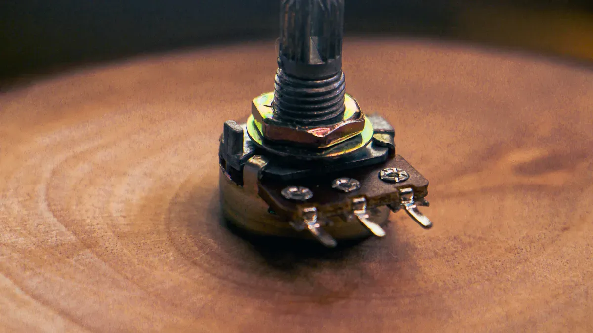
Potentiometer (10k ohm) for contrast adjustment
220-ohm resistor for backlight control (optional)
Header pins (if your lcd 16x2 does not have them soldered)
You can find these parts in most Arduino tutorial kits. The potentiometer lets you adjust the contrast of the lcd display. The resistor protects the backlight and keeps the lcd 16x2 safe. These components make the connection process easier and help you avoid wiring mistakes.
Tip: Use a stable 5V power source for your lcd 16x2. This prevents flickering and keeps your display clear.
Parallel Wiring Steps
Parallel wiring is the most common method for beginners. You connect each pin of the lcd 16x2 directly to the Arduino. This method gives you full control over the lcd display and helps you learn about pinout and connection.
Follow these steps for parallel wiring:
Place the lcd 16x2 and Arduino on your breadboard.
Connect lcd pin 2 (VCC) to Arduino 5V.
Attach lcd pin 3 (V0) to the middle pin of the potentiometer. Connect the other two potentiometer pins to 5V and GND.
Connect lcd pin 4 (RS) to Arduino digital pin 12.
Connect lcd pin 5 (RW) to GND. This sets the lcd 16x2 to write mode.
Connect lcd pin 6 (Enable) to Arduino digital pin 11.
Connect lcd pin 11 (DB4) to Arduino digital pin 5.
Connect lcd pin 12 (DB5) to Arduino digital pin 4.
Connect lcd pin 13 (DB6) to Arduino digital pin 3.
Connect lcd pin 14 (DB7) to Arduino digital pin 2.
Connect lcd pin 15 (LED+) through a 220-ohm resistor to 5V. This powers the backlight.
Connect lcd pin 16 (LED-) to GND.
You now have a complete connection between the lcd 16x2 and Arduino. This setup works for most Arduino tutorial projects. Always check your pinout before powering up the lcd display.
Note: If your lcd 16x2 shows a blank screen, adjust the potentiometer. This changes the contrast and makes the text visible.
Pin Mapping Table
A pin mapping table helps you see which Arduino pins connect to each lcd 16x2 pin. This table makes your wiring clear and prevents mistakes during connection.
LCD Pin No. | LCD Pin Name | Arduino Pin | Function |
|---|---|---|---|
1 | Ground (VSS) | GND | Power ground |
2 | VCC | 5V | Power supply |
3 | V0 | Potentiometer | Contrast adjustment |
4 | RS | 12 | Register select |
5 | RW | GND | Write mode |
6 | E | 11 | Enable |
11 | DB4 | 5 | Data bit 4 |
12 | DB5 | 4 | Data bit 5 |
13 | DB6 | 3 | Data bit 6 |
14 | DB7 | 2 | Data bit 7 |
15 | LED+ | 5V (via 220Ω) | Backlight power |
16 | LED- | GND | Backlight ground |
This pin mapping table matches most Arduino tutorial examples. You can use it as a quick reference for lcd wiring and connection.
Wiring Diagram
A wiring diagram shows you how to connect the lcd 16x2 to Arduino step by step. You can follow the diagram to make sure each connection is correct. This helps you avoid pinout errors and keeps your lcd display safe.
[Arduino UNO]         [lcd 16x2]
   GND -------------- Pin 1 (Ground)
   5V --------------- Pin 2 (VCC)
   Potentiometer ---- Pin 3 (V0)
   D12 -------------- Pin 4 (RS)
   GND -------------- Pin 5 (RW)
   D11 -------------- Pin 6 (Enable)
   D5 --------------- Pin 11 (DB4)
   D4 --------------- Pin 12 (DB5)
   D3 --------------- Pin 13 (DB6)
   D2 --------------- Pin 14 (DB7)
   5V (220Ω) -------- Pin 15 (LED+)
   GND -------------- Pin 16 (LED-)
You can use jumper wires to make each connection. Keep your wires short and neat. This prevents signal loss and makes your lcd 16x2 display stable.
Callout: Always double-check your pinout and connections before uploading code. This step prevents blank screens and garbled text.
You now have a complete guide for wiring the 16x 2 lcd display screen to Arduino. This tutorial helps you learn about lcd wiring, pinout, and interfacing with arduino. You can use the 1602 lcd in many Arduino tutorial projects. The lcd 16x2 gives you clear text and custom characters. Try this connection method and see your lcd display come to life.
lcd 16×2 I2C Wiring
What Is I2C?
You can use I2C to connect your 16x2 lcd to Arduino with just two data lines. I2C stands for Inter-Integrated Circuit. This protocol lets you control many devices using only two pins on your Arduino: SDA (data) and SCL (clock). When you use I2C, you do not need to connect each lcd pin separately. This makes your wiring much simpler than the parallel method.
Here is a quick comparison:
Feature | I2C Wiring | Parallel Wiring |
|---|---|---|
Number of GPIOs Required | 2 | Multiple |
Complexity of Wiring | Simplified | Complex |
Internal Handling | Uses I2C backpack | Direct control |
Support | Widely supported in libraries | More setup needed |
You can see that I2C saves you time and reduces mistakes. Many lcd 16x2 modules come with an I2C backpack already attached.
I2C Wiring Steps
To wire your lcd 16x2 using I2C, follow these steps:
Connect the GND pin on the I2C module to Arduino GND.
Connect the VCC pin to Arduino 5V.
Connect the SDA pin to Arduino A4.
Connect the SCL pin to Arduino A5.
I2C Module Pin | Arduino Uno Pin |
|---|---|
GND | GND |
VCC | 5V |
SDA | A4 |
SCL | A5 |
You need to install the LiquidCrystal_I2C library from the Library Manager. This library works with the liquidcrystal library to make programming easy. Most I2C lcd modules use address 0x27 or 0x3F. If you do not know your address, you can run a scanner sketch from the tutorial to find it.
Tip: The LiquidCrystal_I2C library lets you control the lcd display with simple commands. You do not need to manage each pinout or write complex code.
Advantages of I2C
Using I2C with your lcd 16x2 gives you many benefits:
Advantage | Description |
|---|---|
Simplified Wiring | Only four connections needed for the lcd display. |
Reduced Pin Usage | Saves Arduino pins for other parts of your project. |
Easy to Use Libraries | The liquidcrystal library and LiquidCrystal_I2C library make coding simple. |
Built-in Contrast Adjustment | Many I2C lcd modules have a contrast knob on the back. |
Versatility in Displaying Info | You can show both static and changing data for many types of projects. |
You can focus on your project instead of worrying about wiring or pinout. The guide and tutorial help you get started with the 16x 2 lcd display screen and I2C quickly. Try this method if you want a neat setup and more free pins on your Arduino.
Power, Contrast, and Backlight
Supplying Power
You need to supply the right voltage and current to your 16x2 lcd. This step keeps your display safe and working well. Most lcd 16x2 screens run on 5 volts direct current. You can use the 5V pin on your arduino to power the lcd. The current requirement is low, so you do not need a special power supply. Check the table below for recommended values:
Specification | Value |
|---|---|
Voltage requirements | 5 VDC +/- 0.5V |
Current requirements | 2 mA @ 5 VDC |
If you use a breadboard, connect the lcd display VCC pin to the 5V output from your arduino. Connect the ground pin to GND. This setup works for most projects and tutorials. Always check your wiring before turning on the display.
Tip: Use a stable power source to prevent flickering or dim text on your lcd.
Adjusting Contrast
You can adjust the contrast of your 16x2 lcd to make the text easy to read. Most lcd displays have a pin for contrast control. You connect this pin to a potentiometer. Turn the knob to change the contrast. This method lets you set the best visibility for your lcd display.
Method | Effect on Readability |
|---|---|
Lets you optimize contrast for lighting, making text clear. | |
Automatic Adjustment | Changes contrast as needed, improving readability in different places. |
Manual adjustment works well for most arduino projects. If your lcd 16x2 has automatic contrast, the display changes based on the environment. You can see the text better in bright or dark rooms.
Note: If your lcd shows a blank screen, try adjusting the contrast knob.
Backlight Control
The backlight helps you see the lcd display in low light. You power the backlight using the lcd 16x2 LED+ and LED- pins. Connect LED+ to 5V through a resistor. Connect LED- to GND. The resistor protects the backlight and keeps your lcd safe. Some arduino tutorials show how to control the backlight with a digital pin. You can turn the backlight on or off in your code.
Use a 220-ohm resistor for the backlight.
Connect LED+ to 5V, LED- to GND.
For advanced projects, use a transistor to switch the backlight.
This guide helps you set up power, contrast, and backlight for your 16x2 lcd. You can follow these steps to make your lcd display clear and easy to read.
LCD 16x2 Test Code
Basic Initialization and Commands
You need to set up your 16x2 lcd before you can display text. The initialization process prepares the lcd for showing messages. You use simple commands in your code to control the lcd display. Here is a table of basic commands you will use in your Arduino code:
Command | Description |
|---|---|
lcd.begin(16, 2) | Initializes the lcd with 16 columns and 2 rows. |
lcd.print("Text") | Displays specified text on the lcd. |
lcd.setCursor(column, row) | Sets the cursor position for the next print command. |
lcd.clear() | Clears the entire display. |
lcd.home() | Moves the cursor to the top-left corner of the display. |
These commands help you start your lcd 16x2 and display text. You can use lcd examples to learn how each command works. The guide shows you how to use these commands in your Arduino code.
Uploading Example Code
You can upload code to your Arduino to test the 16x2 lcd. Follow these steps to run lcd examples:
Include the LiquidCrystal library in your code using
#include <LiquidCrystal.h>.Define the pin connections for the lcd:
const int rs = 12, en = 11, d4 = 5, d5 = 4, d6 = 3, d7 = 2;.Set up the lcd in the
setup()function withlcd.begin(16, 2);.Print a message to the lcd using
lcd.print("hello, world!");.In the
loop()function, set the cursor position and print the elapsed time usinglcd.setCursor(0, 1);andlcd.print(millis() / 1000);.
Here is a sample code block for your lcd 16x2:
#include <LiquidCrystal.h>
LiquidCrystal lcd(12, 11, 5, 4, 3, 2);

void setup() {
  lcd.begin(16, 2);
  lcd.print("hello, world!");
}

void loop() {
  lcd.setCursor(0, 1);
  lcd.print(millis() / 1000);
}
You can use this code in your Arduino IDE. The tutorial helps you understand each step.
What to Expect
When you run the code, you will see display text on your 16x2 lcd. The first line shows "hello, world!" and the second line updates with the elapsed time in seconds. The lcd display should match the strings sent in your code. If you see clear text, your lcd 16x2 works well. If the display shows garbled text or nothing, check your wiring and code. The guide and lcd examples help you troubleshoot and learn how to use the lcd display in your projects.
Tip: Always check your code and connections if the lcd does not display text as expected. You can use lcd examples to test different commands and messages.
Troubleshooting Guide
Blank Screen Issues
You may see a blank screen when you power up your 16x2 lcd. This problem can happen for several reasons. Use the table below to find the cause and solution:
Common Cause | Description | Resolution |
|---|---|---|
Power and Ground Issues | The display does not get enough power or ground. | Check for a stable 5V supply and solid ground. Use a multimeter to test connections. |
Incorrect Wiring | Pins are not connected as shown in the guide or datasheet. | Double-check your wiring with a diagram. Make sure each wire goes to the right place. |
Software/Code Errors | The arduino code does not set up the lcd 16x2 correctly. | Review your code. Make sure you use the right initialization commands. |
Faulty LCD Module | The display might be damaged. | Try the lcd on another arduino or replace it if needed. |
Tip: If the backlight works but you see no text, adjust the potentiometer for contrast.
Garbled Text
Sometimes, the 16x2 lcd shows random or unreadable characters. You can fix this by following these steps:
Step | Description |
|---|---|
1 | Check Wiring: Make sure all connections match the lcd datasheet and are secure. |
2 | Adjust Contrast: Turn the potentiometer to set the best contrast. |
3 | Check Code Initialization: Confirm your code uses the right setup for the display. |
4 | Re-upload and Add Delays: Upload your code again and add small delays if needed. |
5 | Hardware Testing: Test the lcd with known working code and check all connections. |
6 | Other Tips: Make sure the arduino and lcd share a common ground. For I2C, check the address. |
Note: Garbled text often means a wiring problem or a missing initialization command in your code.
Contrast and Backlight Problems
If you cannot see text or the display looks too dark or too bright, you may have a contrast or backlight issue. Turn the potentiometer slowly to adjust the contrast. If the backlight does not turn on, check the LED+ and LED- pins. Use a 220-ohm resistor for the backlight to protect the lcd. For flickering displays, add a 100µF capacitor across VCC and GND.
Adjust the potentiometer for best text visibility.
Check the backlight wiring and resistor.
Add a capacitor if the display flickers.
Wiring Mistakes
Wiring mistakes cause many display problems. The table below shows common symptoms, causes, and solutions:
Symptom | Likely Cause | Solution |
|---|---|---|
Blank screen, backlight on | Contrast too high/low | Adjust the potentiometer |
Black boxes on first row | No initialization | Check if code uploads properly |
Random characters | Loose data wires | Verify D4-D7 connections |
Partial display works | Wrong pin assignments | Match code to actual wiring |
No backlight | Missing power to pin 15/16 | Add 220Ω resistor to pin 15 |
Flickering display | Unstable power | Add 100µF capacitor across VCC/GND |
Callout: Always follow the wiring diagram in the tutorial. This step helps you avoid wiring problems and keeps your lcd 16x2 working well.
If you follow this guide, you can solve most issues with your 16x2 lcd display. Careful wiring and setup will help your arduino projects run smoothly.
Custom Characters and Tips
Creating Custom Characters
You can make your 16x2 lcd display show more than just letters and numbers. The lcd lets you design your own symbols or icons. You do this by creating custom characters. The lcd 16×2 uses a special memory area called CGRAM to store these designs. You can use up to 8 custom characters at one time. Each one sits in a slot from 0 to 7.
Here is a simple table to help you understand the steps:
Step/Aspect | Description |
|---|---|
Custom Character Creation | Use lcd.createChar(location, byteArray) to define and store characters. |
Slot Capacity | CGRAM can hold up to 8 custom characters in slots 0 to 7. |
Memory Addresses | Slots use addresses 0x40–0x7F in the controller’s memory. |
Reuse Slots | Reassign characters to slots if you need more than 8 designs. |
Dynamic Overwriting | Update CGRAM to show new characters or animations. |
You can draw each character using a grid of pixels. The lcd 16x2 will show your design on the display. If you want to make a smiley face or a progress bar, you can use this feature. Remember, the lcd only holds 8 custom characters at once. You can overwrite them if you need new designs during your project.
Tip: Try making simple shapes first. You can use the lcd.createChar function in your arduino code.
Useful Tips for lcd 16x2
You can get the best results from your lcd 16×2 by following some easy tips. These ideas help your display look clear and last longer in your arduino projects.
Use the Liquid Crystal library to control the lcd. This library makes your code simple and easy to read.
Adjust the contrast with a potentiometer. This step helps you see the text better on your display.
Pick 4-bit mode if you want to save arduino pins. Use 8-bit mode if you need faster data or have enough pins.
Add a 220-ohm resistor to the backlight. This protects your lcd and keeps the display bright.
Always set up the lcd object in your arduino IDE before you use any display commands.
You can follow these tips to avoid common problems. The guide and tutorial show you how to wire, code, and use your lcd 16x2 in many projects. You will find that the lcd 16×2 is a powerful tool for showing information on your arduino display.
You can set up and test the 16x2 lcd display by following easy steps. Try parallel wiring if you want to learn by doing. Use I2C wiring if you want a simpler setup. You can make custom characters and try advanced features with the 16x2 lcd. The guide and tutorial help you learn about the lcd and its controller. Look for more information about display drivers, language choices, and STM32 libraries if you want to learn more.
Feature | Description |
|---|---|
Custom Characters | Make special symbols for your lcd projects |
Language Support | Show text in many different languages |
Keep trying new designs and ways to wire your lcd to get better at using it.
16x2 LCD Display Screen – Beginner's Guide
The 16x2 LCD module is a classic entry‑level component for electronics projects. It is a simple character display that can show 16 English characters per line, across two lines. It is ideal for displaying sensor data, device status, or simple menus.
🔌 Understanding the Module Pins
The LCD module typically has 16 pins. The table below summarises the function of each pin for quick reference during wiring.
Pin | Symbol | Description |
|---|---|---|
1 | VSS | Ground (GND) |
2 | VDD | Power positive (5V) |
3 | V0 / VEE | LCD bias voltage; connect to a potentiometer to adjust contrast. |
4 | RS | Register Select: High (1) = Data register, Low (0) = Instruction register. |
5 | R/W | Read/Write: Usually connected to GND for write‑only mode. |
6 | E | Enable: A high‑to‑low pulse tells the LCD to execute an instruction or read/write data. |
7–14 | D0–D7 | 8‑bit bidirectional data bus for commands or display data. |
15 | A (BLA) | Backlight LED anode (connect to 5V) |
16 | K (BLK) | Backlight LED cathode (connect to GND) |
🔗 Two Common Wiring Methods
Depending on whether you want simplicity or a deeper understanding, there are two mainstream wiring approaches.
1. Parallel Wiring (4‑bit or 8‑bit mode)
Pros – Teaches the low‑level timing of the LCD.
Cons – Uses many I/O pins (6 pins for 4‑bit mode).
Best for – Learning the fundamentals or when you don’t have an I2C module.
2. I2C Serial Wiring (Recommended for beginners)
Pros – Very simple wiring: only 4 wires (VCC, GND, SDA, SCL). Saves I/O pins.
Cons – Requires an I2C backpack (small extra cost).
Best for – Fast, beginner‑friendly projects.
📝 Programming Your LCD
Using an I2C Module (Recommended)
Wiring (Arduino Uno as example):
VCC → 5V
GND → GND
SDA → A4 (SDA)
SCL → A5 (SCL)
⚠️ Troubleshooting Common Issues
Issue | Most Likely Fix |
|---|---|
Screen is blank or shows blocks | 99% of the time it’s contrast adjustment. Turn the potentiometer on pin 3 until characters appear clearly. |
I2C communication fails | Run an I2C scanner to confirm the correct address. Check SDA/SCL connections. |
Content doesn’t update or shows garbage | Verify pin definitions match your wiring. Ensure |
✨ Project Ideas
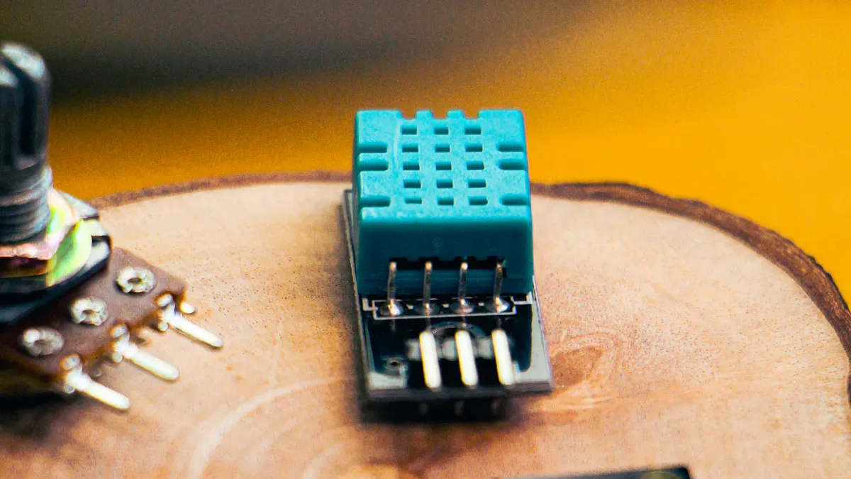
Weather station – Display temperature, humidity, air pressure.
Smart home panel – Show device status and system info.
Simple games – Create character‑based games (e.g., a racing game with custom characters).
Arduino learning kit – The classic “Hello World” project.
💡 Where to Buy
Platform | Best For |
|---|---|
LCSC, Taobao, 1688 | Affordable domestic modules (China) |
DigiKey, Mouser, Farnell | Bulk orders, industrial / original quality |
Seeed Studio, Adafruit, SparkFun | Maker‑friendly modules with tutorials |
💎 Summary
The 16x2 LCD is a classic display module known for its low cost, simple operation, and reliable stability. It is an essential tool for electronics hobbyists and developers, whether for learning or building practical projects.
I hope this guide helps you light up your first screen! If you have any questions about a specific step (finding the I2C address, adjusting contrast, etc.), feel free to ask.
FAQ
How do I know if my 16x2 LCD is working?
You should see the backlight turn on and a row of dark blocks on the first line when you power up. If you upload test code, clear text should appear. Adjust the contrast knob if you see nothing.
Can I use a 3.3V microcontroller with a 16x2 LCD?
Most 16x2 LCDs need 5V for best results. Some modules work at 3.3V, but the display may look dim. Always check your LCD’s datasheet before connecting to a 3.3V board.
Why does my LCD show only black boxes?
This usually means the LCD did not initialize. Check your wiring, especially the data pins and contrast adjustment. Make sure your code uses the correct setup commands for your LCD.
What is the difference between 4-bit and 8-bit mode?
In 4-bit mode, you use only four data pins, which saves Arduino pins. In 8-bit mode, you use all eight data pins for faster data transfer. Most projects use 4-bit mode for simplicity.
Do I need a resistor for the LCD backlight?
Yes, you should use a 220-ohm resistor with the backlight pin. This protects the LED from too much current and helps your LCD last longer.
See Also
A Beginner's Guide to Using Transparent OLED Displays
Understanding LCD Display Screens: Functionality Explained
Key Insights on LCD Display Screens: Pros and Cons